When using different VPN connections (L2TP/IPsec, PPTP, SSTP), the most common task is to provide clients with remote access to a local VPN server's network. In this case, when a client connects to the VPN server, traffic is automatically routed to the local network. But sometimes, the task is to organize access not only to the local network of the VPN server but also in the opposite direction, i.e. from the VPN server's network to the remote VPN client's network to provide data exchange between two sides of the VPN tunnel.

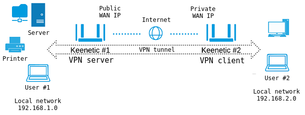
Suppose that Keenetic#1 router is connected to the Internet via an ISP that provided a public IP address. On this router, a VPN server (L2TP/IPsec, PPTP, SSTP) is enabled.
Keenetic#2 router has Internet access via ISP, which provides a private IP address.
NOTE: Important! The Keenetic router, which runs the L2TP/IPsec or PPTP VPN server, must be connected to the Internet with a public IP address, and when using a KeenDNS domain name, it must be configured in the 'Direct access' mode. If any of these conditions are not met, connecting to such a server from the Internet will be impossible.
As for the SSTP tunnel, its main advantage is its ability to work through the cloud, i.e. it allows establishing a connection between the client and the server, even if there are private IP addresses on both sides of the tunnel.
Router Keenetic#2 automatically establishes a connection to the VPN server (Keenetic#1), which allows users of its local network (User#2) to get access both directly to Keenetic#1 (to connect to USB drives and printers), and to local resources — computers, NAS servers and so on.
After implementing the following setup, the same access will become possible in the opposite direction, i.e. to Keenetic#2 local network from Keenetic#1 local network. For example, User#1 can access files located in the shared folder of User#2.
Keenetic#1 setup
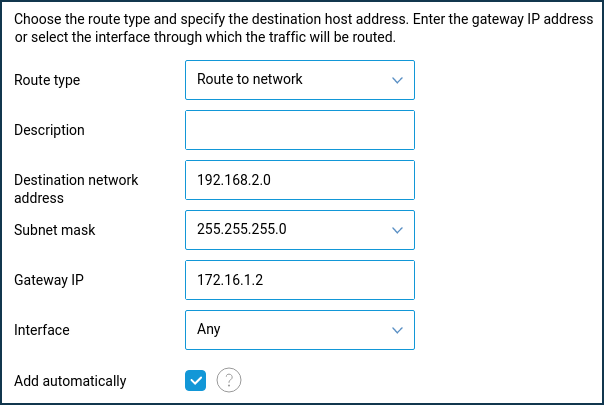
For the VPN server's local network clients to have access to local network resources behind the VPN client, you need to add a static route, indicating the location of the client's network. In our example, the local network 192.168.2.0/255.255.255.0 will be available through the IP address given by the VPN server to the connected client (in our case, it will be the client with IP address 172.16.1.2).
On the 'Routing' page, click 'Create route'. In the 'Static route parameters' window that appears, select' Route to network' in the 'Route type' field. In the 'Destination network address' field, specify the remote subnet you want to organize access to and which is on the VPN client side.
In the 'Gateway IP' field, enter the IP address of the VPN client provided by the VPN server during the connection. In the VPN server settings, turn off the 'Multiple entry' option and define a permanent IP address for the VPN client. You can do this on the VPN server settings page in the 'Users' section.
When setting up a static route, you should enable the 'Add automatically' option and leave 'Any' in the 'Interface' field.

NOTE: Important! Once you add a route, it will not work immediately. You will need to reconnect the VPN tunnel. Disconnect the VPN connection and then activate it again.
Keenetic#2 setup
On the VPN client-side router, please note the following settings:
1. When configuring a VPN connection, you do not need to enable the 'NAT for clients' option. This setting is used to access VPN server clients to the Internet. When connecting to the VPN server, the client will automatically receive information about the local network located behind the server. This eliminates the need to configure static routing.
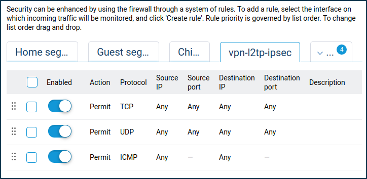
2. Since the default firewall on the Keenetic#2 VPN client interface blocks all incoming connections to the local network (in our example to 192.168.2.x network), it requires opening the ports/protocols needed for the work.
On the 'Firewall' page, select the interface on which incoming traffic will be tracked from the list (this is a VPN connection), and click 'Add rule' to create access rules for any protocols (as a rule, it will be enough to open access via TCP/UDP/ICMP protocols).

TIP: Note:
a. If you have established a VPN connection, see (can ping) the remote router and does not receive any ping responses from computers on the remote network, most likely, the Windows Firewall blocks traffic on the computers.
When you ping some IP address, ensure that your computer does not block incoming connections (by default, Windows Firewall blocks ICMP requests). Try to repeat the ping by disabling the blocking.
b. When using protected VPN tunnels, there may be limitations on the speed of data exchange. The additional load on the device, associated with routing, processing and encryption of data in the VPN, may decrease data transmission speed compared with the channel bandwidth. For example, the SSTP VPN server works through Keenetic Cloud servers; its speed depends on the number of customers using the cloud and their activity.
c. Automatic name resolution of the names of computers and devices in the Microsoft Windows network through the VPN tunnel is not supported since the networks are joined at layer 3 of the OSI model, using NAT (network address translation) and routing. Restrictions imposed by these factors prevent the Computer Browser service, which uses non-routing types of data transmission designed for peer-to-peer networks. Therefore, access to remote network devices by their network names will not work.
d. You can combine several home networks to access from each network to any other. More than 10 client concurrent connections can be made to a VPN server on a single router.
The maximum number of PPTP VPN tunnels:
up to 100 (for KN-1111, KN-1211, KN-1611, KN-1711);
up to 150 (for KN-2111) and up to 200 (for KN-1010 and KN-1810).
There is no restriction for L2TP/IPsec VPN tunnels.
e. SIP telephony, as well as other data transmission technologies, can work through an installed VPN tunnel.